I’ve been working on building a mutant version (that is: with non-vintage components) of the timbre/symmetry section of the famous Buchla 259 complex waveform generator.
I used the schematic Mark Verbos posted on his website as a starting point. I replaced all opamps with the TL072CN. All other components are common resistors (I used 1% metal film for all resistors), caps and diodes. When I finished the circuit I didn’t get any good waveform on the output on my first test. I tried inserting a sine wave at the input of the folding section and got better results after increasing the amplitude of the input signal. After checking the input circuit I found a 1:20 voltage divider at the audio input. So my 4 Vpp input sine wave was immediately attenuated to 200mVpp. After adjusting the voltage divider everything worked like it should. As far as I can tell from stuff I’ve seen on YouTube of real Buchla 259′s the waveforms definitely resemble the original. I’m happy with that as it was not my intention the built a 100% identical clone of the original. Here are some examples of what waveforms can be achieved with this circuit.
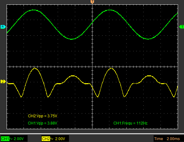
Input signal: green (sine) Output signal: yellow
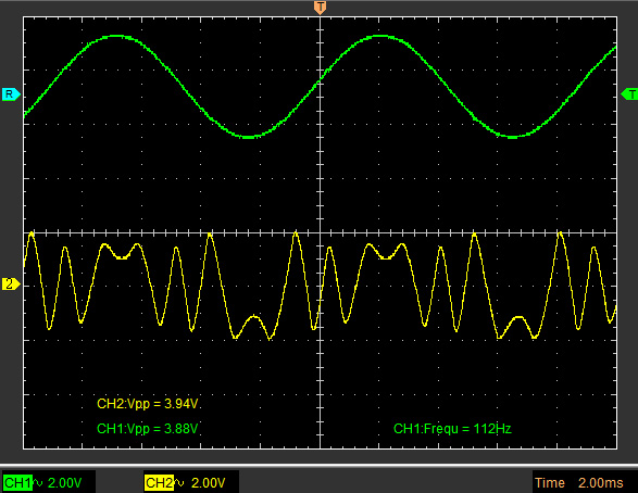
Input signal: green (sine) Output signal: yellow
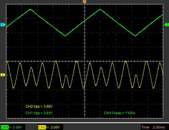
Input signal: green (triangle) Output signal: yellow
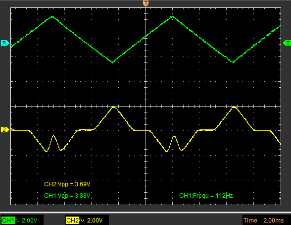
Input signal: green (triangle) Output signal: yellow
Here are two recordings of the timbre section. In the first recording I’m using a sine wave as input signal. The second one uses a triangle wave as input. During both recordings the controls are tweaked in real-time.
The circuit has 3 main controls: Timbre, Timbre CV and what I call Timbre Sensitivity. This sensitivity control is a trimmer on the PCB on the original Buchla but I decided to bring it to the front panel as it provides in a nice range of waveform diversity. Timbre can be voltage controlled. I have to do some final testing and tweaking to finalize the schematic. This version does not have the Symmetry and Order sections as the original had. I’m using this timbre section to built a mutant 259 complex waveform generator using two 258J VCOs. A modulation index section takes care of the modulation matrix functionality.
I designed a dual layer PCB for this circuit. This PCB contains the mutant 259 timbre section, two 292C-like VCAs and an additional TL074 configured as 4 non-inverting opamps which can be used to adjust output voltages as needed. The PCB has the same dimensions as the 258J oscillator board, so it will be very easy stacking this on top of 2 oscillator boards. The power connectors also line up with those on the 258J simplifying connecting power from board to board.